Recently, I modified Yusheng’s Watt connecting rod, but the first thing I thought about was how to improve Yusheng’s rear stopper. The purpose of the improvement is to make the vehicle more stable. Later analysis found that no matter how stable it is, it is not as stable as the Watt connecting rod, so Simply study the Watt connecting rod directly. Although I don’t need the analysis of the thrust rod now, it is estimated that some friends still don’t know what the characteristics of the thrust rod are, so I wrote it for your reference. The forum is a place for communication and sharing useful things with each other. We all make progress together.
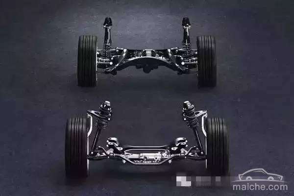
The structure of the Panhard connecting rod (called the thrust rod for convenience in the figure below) looks very simple. There is only one rod, one end is connected to the rear axle, and the other end is connected to the carriage, so that the carriage and the axle maintain a tight but movable Connection. This connection is very important when the vehicle is traveling at high speeds. I’m not a professional, so I just use my personal language to talk about what I think is the most important thing. One end of the thrust rod is connected to the axle (which can be regarded as the center of the circle), and the other end is connected to the carriage (which can be regarded as the other end of the radius connected to the center of the circle). When the carriage moves up or down, the carriage is centered on the axle , make a circular motion with the thrust rod as the radius. Therefore, the car will also move left and right when the carriage is raised and lowered.
This displacement is a factor for the instability of the vehicle. To put it bluntly, the carriage is shaking from side to side relative to the wheels. Below I will show you some pictures. Does the engineer of the manufacturer know this left and right displacement? Of course I know, so I made a corresponding design to reduce the shaking, as explained in the figure below. Then some people may ask, what factors are related to the shaking of this left and right displacement? I have summed up two determining factors for this shaking: 1. Thrust rods of the same length are related to the included angle (that is, the greater the change in the included angle, the greater its displacement, which increases geometrically). 2. The same height, The longer the thrust rod, the smaller the displacement. People generally don’t change the thrust rod, but some riders raise the shock absorber by an inch or two inches or even higher, then the characteristics of this thrust rod will be used immediately. Let’s analyze it with the graph below.

This is a schematic diagram of the operation of the Panhard connecting rod on the Internet. The left and right displacements occur at the same time during the upward movement of the carriage. The left and right displacements are normal movements, but the thrust rod pulls the carriage hard to move left and right, which is an unstable factor.

This is what I hand-painted, the relationship between the rising angle and displacement. The larger the rising angle, the larger the displacement, which increases geometrically. But there is basically no displacement when the thrust rod L and a coincide. This is the reason for the image below.

I experimented with the thrust rod of the original Yusheng car.

When the top of the thrust rod rises (equivalent to the rise of the carriage) by 28 cm, what is the left and right displacement?

Equivalent to a compartment height of 28 cm

The left and right displacement is close to 4 cm. When the car falls down, if it bounces a few more times and shakes left and right like this, will the rear of the car be stable? Therefore, a car with such a thrust rod must not be bumped quickly and sharply, causing the cabin to go up and down violently, which is very uncomfortable and there is a risk of loss of control.

You will find that every car with a thrust rod has such a tripod at the connection with the carriage. Could it be that the engineer is stupid and simply welds it directly to the carriage? No, because as you can see from the hand drawing above, the smaller the axle and thrust rod angles, the less the side to side displacement. The purpose of this tripod is to make the angle between the axle and the thrust rod as small as possible, so that the vehicle is more stable when going up and down. Therefore, Kai Yusheng cannot make the up and down range of the carriage too large, otherwise the left and right displacement changes will be very obvious.

It can be seen from the above figure that for the same height, the longer the thrust rod, the smaller the left and right displacement. This is one of the reasons why Land Cruiser is more stable. Its body is wider and its thrust rod is longer than that of Yusheng. With the same height, the left and right displacement is smaller than that of Yusheng, so it is more stable. I used this method to modify Yusheng at the beginning, that is, to lengthen the thrust rod of Yusheng to improve the stability of Yusheng, but thinking about how to modify it, it is not as small as the displacement of the Watt connecting rod (theoretically, there is no displacement in a certain operating section) , That’s why I gave up the idea of lengthening the Yusheng stop putter. Friends who are interested can try it.


